- Thread Author
- #1
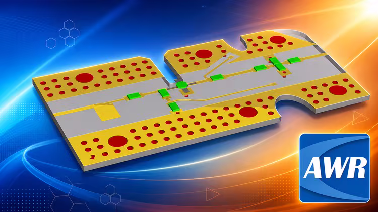
Free Download Design of 5GHz LNA in AWR Software and LNA matching
Published 5/2026
MP4 | Video: h264, 1920x1080 | Audio: AAC, 44.1 KHz, 2 Ch
Language: English | Duration: 53m | Size: 484.61 MB
From Zero to Hero LNA design in AWR microwave office, LNA matching for best NF and gain in Optenni Software
What you'll learn
Design of 5GHz LNA in AWR Software
LNA matching for best NF and gain in Optenni Software
Distortion Parameters
Harmonic Distortion
AM-AM/AM-PM
Intermodulation Distortion (Second and Third order intermodulation)
Intercept Point IPn (IP3)
Intermodulation Distortion Power (P_IMD)
Carrier to Intermodulation Ratio (C/I)
Spurious Free Dynamic Range (SFDR)
Adjacent Channel Power Ratio(ACPR)
Noise and Co-Channel Power Ratio (NPR and CCPR)
Multi-tone Intermodulation Ratio (M-IMR)
Error Vector Magnitude
Class of Operation
RF power device family
Introduction to Power Amplifier
Definition of Power Amplifier Parameters
Requirements
You will learn everything you need to know
Description
Power Amplifier
- Introduction to Power Amplifier
- Definition of Power Amplifier Parameters
- Distortion Parameters
- Harmonic Distortion
- AM-AM/AM-PM
- Intermodulation Distortion (Second and Third order intermodulation)
- Intercept Point (IP3)
- Intermodulation Distortion Power ()
- Carrier to Intermodulation Ratio (C/I)
- Spurious Free Dynamic Range (SFDR)
- Adjacent Channel Power Ratio(ACPR)
- Noise and Co-Channel Power Ratio (NPR and CCPR)
- Multi-tone Intermodulation Ratio (M-IMR)
- Error Vector Magnitude
- Class of Operation
- RF power device family
LNA matching for best Noise Figure and Gain in Optenni Lab
Low Noise Amplifier (LNA) matching is a fundamental RF design task.In general the best noise performance is achieved in a matching configuration that does not provide the highest gain. In this tutorial we consider the steps needed to find the input matching circuit that delivers the optimal noise figure (NF) of the LNA. We also consider the more challenging Carrier Aggregation (CA) matching problem where receiver bands A and B are connected to a multi throw SP2T switch branches. The challenge is that the noise matching for band A and B amplifiers must be close to ideal when only one of the bands is switched on, and when both of the bands are switched on. This course examples require use of Optenni Lab Professional Edition.
Who this course is for
Beginners & Professionals in RF
Academics and Researchers
Engineering Students

Code:
RapidGator
https://rg.to/file/da9c7ffb86d1f79c8b07e0e57377c817/nsajg.Design.of.5GHz.LNA.in.AWR.Software.and.LNA.matching.rar.html
[b]AlfaFile[/b]
https://alfafile.net/file/A4MB5/nsajg.Design.of.5GHz.LNA.in.AWR.Software.and.LNA.matching.rar